Pre-Insulated Duct System
In this system, an HDPE or PVC duct is pre-insulated and joined in the field, either by butt fusion or heat, shrink tubes for HDPE, or in the case of PVC duct, bell and spigot joints. Heat losses are reduced and time to freeze is increased because of the pre-insulated duct through which the un-insulated municipal service pipe is pulled.
DUCT: Either HDPE or PVC plastic duct to suit the size and number of service pipes being pulled in. HDPE ducts to be joined by either butt fusion of heat shrink tubes; PVC ducts to be joined either by gasketed joint (bell and spigot) or heat shrink tubes. If the corporation stop is not insulated, heat shrink tubes shall be used to seal between the duct end and the service pipe to prevent duct flooding.
INSULATION: 50 mm (2 in) thick U.I.P.® factory applied rigid polyurethane foam insulation with a 1.27 mm (50 mils) thick black polyethylene outer protective jacket. Insulation joints to be field insulated with compatible insulation halfshells and wrap around heat shrink sleeves.
HEATING CABLE: THERMOCABLE® fluoropolymer insulated “constant watt” heating cable is taped logitudinally with aluminium heat conducting tape to the service pipe. THERMOCABLE® capacity to be sized according to the diameter of the duct. Additional capacity should be included if tracing system is passive (to be energized only if service pipe freezes). All systems should be thermostatically controlled; if the service pipe is plastic, dual sensing thermostat must be used.
PIPE: Usually either type K soft copper or HDPE (CTS or IPS) municipal service pipe is pulled into the duct without joints.
Time to Freeze and Heat Loss For Service Pipes Inside a U.I.P.® Pre-Insulated Service Duct
| Nominal Pipe Diameter |
Nominal Duct Diameter |
Duct Ambient -18°C (0°F) | Duct Ambient -34°C (-30°F) | ||||||
| Time to Freeze HRS. | Heat Loss | Time to Freeze HRS. | Heat Loss | ||||||
| mm | in | mm | in | No Insulation |
50 mm (2 in) U.I.P.® |
(watts/m) | No Insulation |
50 mm (2 in) U.I.P.® |
(watts/m) |
| 19 | 0.75 | 40 | 1.5 | <1 | 10 | 2.4 | <1 | 5.8 | 4.4 |
| 25 | 1 | 40 | 1.5 | <1 | 20 | 2.4 | <1 | 10 | 4.4 |
| 40 | 1.5 | 75 | 3 | <1 | 26 | 3.6 | <1 | 15 | 6.5 |
| 50 | 2 | 100 | 4 | 1 | 40 | 4.3 | <1 | 22 | 7.9 |
Note:
- No safety factor included; results are nominal; assumes initial water temperature of 1.11°C (34°F).
- To convert watts to BTU, multiply by 3.414.
- To convert meters to feet, multiply by 3.28.
- To convert watts/m to watts/ft, divide by 3.28.
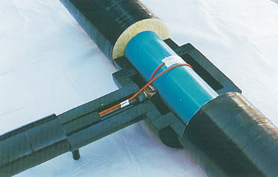
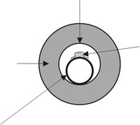
Direct tapped corporation stop on a pre-insulated PVC watermain. The 25 mm (1 in) type K copper service pipe is installed within a pre-insulated 50 mm (2 in) HDPE duct. The THERMOCABLE® heat tracer is taped to the copper pipe and makes one complete turn around the PVC main.
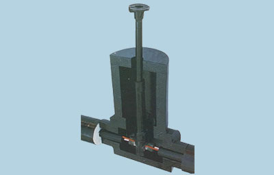
Curb stop and PE service box arrangement on a THERMOCABLE® heat traced type K copper service pipe, in a pre-insulated HDPE duct system.
Pre-Insulated duct does not carry water pressure, it serves as an insulated conduit for the bare municipal service pipe. The service pipe is standard material; type K soft copper or HDPE either DR 11 with IPS dimensions, or CSA approved series 160 with CTS dimensions. The service pipe is pulled through the duct without joints, provided the maximum coil length of the service pipe is not exceeded. The size of the duct (internal diameter) must be large enough to accomodate the size and number of service pipes being pulled through.
If goosenecks are desired, an insulation kit is provided to pre-insulated duct dimensions. The service pipe is then field bent to the contour of the insulation kit and assembled.
If THERMOCABLE® electric tracing is used, the trace cable is taped longitudinally to the service pipe with aluminium heat conducting tape prior to pulling in the assembly. The following table gives the approximate size of duct required for various diameters of service pipe.
Sliding a 50 mm (2 in) pre-insulated duct over a 25 mm (1 in) type K soft copper service pipe and THERMOCABLE® trace cable to a mobile home in Cobalt, Ontario. Photo courtesy Knox Martin Kretch Limited, Consulting Engineers.
Recommended Size of Duct
| Size of Service Pipe | Size of Duct Single Service Pipe |
Size of Duct Double Service Pipe (Recirculating System) |
| 19 mm (0.75 in) | 40 mm (1½ in) | 75 mm (3 in) |
| 25 mm (1 in) | 40 mm (1½ in) | 100 mm (4 in) |
| 40 mm (1.5 in) | 75 mm (3 in) | 150 mm (6 in) |
| 50 mm (2 in) | 100 mm (4 in) | 150 mm (6 in) |
Maximum Coil Length of Standard Municipal Service Pipe
| Nominal Pipe Size | Type K Copper | HDPE (CTS) series 160 |
HDPE (IPS) DR 11 |
| 19 mm (0.75 in) | 20 m (66 ft) | 61, 91, 152 m (200, 300, 500 ft) |
152 m (500 ft) |
| 25 mm (1 in) | 20 m (66 ft) | 61, 91, 152 m (200, 300, 500 ft) |
152 m (500 ft) |
| 40 mm (1.5 in) | 20 m (66 ft) | 30, 61, 91 m (100, 200, 300 ft) |
76 m (250 ft) |
| 50 mm (2 in) | 12.2 m (40 ft) | 30 m (100 ft) |
76 m (250 ft) |
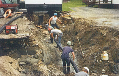
Laying a 100 mm (4 in) pre-insulated HDPE duct into place prior to pulling in the two 25 mm (1 in) circulating service pipes at Iqaluit, N.W.T.
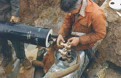
Making the final service connections on a standard NWT (North West Territories) circulating service. Urecon can supply complete NWT water and sewer service kits including all necessary metal and plastic parts to NWT Government specifications.
NOTE: Data may vary from one pipe manufacturer to another.
Laying a 100 mm (4 in.) pre-insulated HDPE duct into place prior to pulling in the two 25 mm (1 in.) circulating service pipes at Iqaluit, N.W.T."
Making the final service connections on a standard NWT (North West Territories) circulating service. Urecon can supply complete NWT water and sewer service kits including all necessary metal and plastic parts to NWT Government specifications."